


Reading a house plan blueprint for the first time can feel overwhelming—lines, symbols, and numbers all competing for your attention. But once you understand how these drawings work together, they become a powerful tool for visualizing your future home. This guide breaks down the essentials in a clear, practical way, helping you move from confusion to confidence as you learn to interpret floor plans, elevations, and the details that shape every space.
Reading a house plan blueprint may seem technical at first, but once you understand the basic structure and symbols, it becomes a practical skill. Blueprints are simply scaled drawings that show how a home is designed and built—covering layout, dimensions, and structural details.
Key Elements of a Blueprint:
1. Start with the Basics: What Is a Blueprint?
A house plan blueprint is a set of drawings that represent a home from different perspectives. These usually include:
- Site plan (placement on land)
- Floor plans (room layout)
- Elevations (exterior views and height)
All drawings are created to scale, meaning measurements on paper reflect real-world dimensions. Learning to read blueprints helps you choose the right plan, communicate clearly with builders, and identify exactly which modifications you need.
2. Check the Title Block First
Before diving into the design, look at the title block, typically located in the bottom-right corner.
Here you’ll find:
- Project name
- Sheet number
- Revision dates
- Designer or architect details
This section helps you understand what you’re looking at and whether you have the latest version of the plan.
3. Understand the Legend (Symbols Key)
Every blueprint includes a legend that explains symbols used throughout the drawings.
As a beginner, focus on:
- Wall types
- Electrical symbols
- Plumbing indicators
- Materials
Learning the legend prevents misinterpretation and saves time as you read the plan.
4. Read the Floor Plan Layout
The floor plan is the most important drawing for beginners. It shows the home from a top-down view.
Pay attention to:
- Room arrangement and names
- Traffic flow (how you move between spaces)
- Placement of doors, windows, and furniture
Tracing how someone would walk through the house is one of the easiest ways to understand the layout.
5. Learn Common Blueprint Symbols
Walls
- Thick lines → structural (load-bearing) walls
- Thin lines → interior partitions
Doors & Windows
- Doors → shown with a curved arc indicating swing direction
- Windows → breaks or thin lines within walls
Lines
- Solid lines → visible elements (walls, cabinets)
- Dashed lines → elements above (vaulted or tray ceilings)
6. Focus on Dimensions and Scale
Blueprints include precise measurements, typically shown like 12'-0" (12 feet, 0 inches).
Key tips:
- Dimensions are usually placed outside the floor plan
- Always check the scale (e.g., 1/4" = 1 foot)
- Use a scale ruler if reading printed plans
Understanding dimensions ensures you correctly interpret room sizes and spacing.
7. Review Elevations for Exterior Understanding
While floor plans show layout, elevations show what the house looks like from the outside.
They help you understand:
- Building height
- Roof style
- Window placement from exterior view
What Is a House Plan Blueprint?
A house plan blueprint is a complete set of construction documents that tells builders exactly how to construct a specific home design. It’s far more than a single floor plan—it’s an entire package of coordinated drawings.
A full blueprint set from Archival Designs typically includes floor plans for each level, exterior elevations showing all four sides, building sections that slice through the structure vertically, foundation plans, roof plans, and basic electrical layouts. Some larger designs add interior elevations for kitchens and baths, framing details, and notes about mechanical systems.
These architectural plans are usually printed at a fixed scale—most commonly a quarter inch equals one foot (1/4” = 1’-0”)—on large sheets sized 18”×24”, 24”×36”, or 30”×42”. Archival Designs’ blueprint packages for 2024–2026 builds meet typical U.S. residential standards, though they must still be reviewed against local codes for wind loads, seismic requirements, and energy efficiency before construction.
Understanding what each sheet type represents makes everything else in this guide easier to follow. Think of the blueprint set as a layered system: floor plans show horizontal layouts, elevations show vertical faces, and sections reveal how everything stacks together.
Your First Look at an Archival Designs Plan Set
When you first open a new plan set, resist the urge to dive straight into the details. Instead, spend a few minutes orienting yourself to what you’re holding.
Start by locating the title block in the lower right corner of each sheet. This administrative hub contains the project name, plan number, designer information, revision date, scale, and sheet number within the set. Every sheet has one, and it ensures everyone on the job site references the identical version of the design.
Next, find the main floor plan sheet—often labeled “Main Floor Plan” or “First Floor Plan.” This bird’s eye view shows you the home’s footprint from above. Locate the front door and the north arrow, then mentally walk through the rooms. Trace the circulation paths from entry to living spaces to bedrooms. This initial walkthrough helps you understand the design intent before examining specific details.
Keep a tape measure or ruler handy as you review. When you see a dimension like 14’-0”, measure that distance in your current space to understand real world dimensions.
The Core Sheets in a Typical Blueprint Package
A complete Archival Designs blueprint contains several interconnected sheet types, each serving a specific purpose.
|
Sheet Type |
What It Shows |
|---|---|
|
Floor Plans |
Horizontal layout of rooms, walls, doors, windows for each level |
|
Exterior Elevations |
Front, rear, and side views showing materials, roof shapes, window placement |
|
Building Sections |
Vertical cut-through views revealing ceiling height, floor levels, roof structure |
|
Foundation Plan |
Footing sizes, slab or basement details, reinforcement specifications |
|
Roof Plan |
Overhangs, ridge lines, vent locations, pitch notations |
|
Electrical Layout |
Outlet placement, switch locations, fixture positions |
These sheets complement each other. Most floor plans show room arrangement, elevations reveal how those rooms appear from outside, and cross sections expose the vertical relationships between spaces. When you read about a vaulted great room on the floor plan, the section drawing confirms exactly how high that vault rises.
Some larger Archival Designs plans include specialty sheets like interior elevations for the kitchen (showing counter heights and cabinet runs) or structural plans with framing details. Before focusing on any single drawing, flip through the entire set once to understand the overall scope.
Decoding Floor Plans: Symbols, Walls, Doors, and Windows
The floor plan sheet is where beginners should invest most of their learning time. Lines, symbols, and abbreviations on this drawing form a visual language that describes walls, openings, plumbing fixtures, and built-in elements.
Archival Designs uses standard symbols consistent with residential architectural designs nationwide. However, each plan includes a legend or notes box clarifying any project-specific conventions. Getting comfortable with all the symbols and standard notation makes browsing online house plans dramatically faster—you’ll instantly recognize layouts without needing to study every line.

Reading Walls and Room Labels
Walls appear as parallel lines on floor plans. Thick, darker lines typically indicate exterior walls—often framed with 2×6 studs to accommodate insulation. Thinner lines or thin lines represent interior walls, usually 2×4 partitions that divide rooms.
Different hatch patterns between wall types can indicate materials:
-
Diagonal lines often represent brick
-
Stippling suggests concrete
-
Horizontal lines may indicate wood siding
Room names appear inside each space—“Great Room,” “Primary Suite,” “Bedroom 2”—along with room dimensions or square footage. On Archival Designs plans, living area square footage refers to heated and cooled interior space. Garages, covered porches, and other elements are listed separately.
To understand the home’s footprint, trace the main exterior walls with your finger. Follow the straight line of the front wall, note where it jogs for a bump-out or porch, and continue around the perimeter. This simple exercise reveals the home’s basic shape before you examine interior details.
Doors, Windows, and Openings
Door symbols appear as breaks in walls with an arc showing swing direction and required clearance. The arc indicates how far the door opens—typically 90 degrees—and which direction it swings into the room.
Common door callouts include:
-
3068: 3’-0” wide × 6’-8” tall (standard interior)
-
3080: 3’-0” wide × 8’-0” tall (taller modern style)
-
Double door: Two panels meeting in the center
-
Pocket door: Slides into the wall cavity (shown as a dashed line)
-
Sliding door: Bypass panels, common for closets and patios
When a door opens into a room, consider furniture placement. A door that swings inward needs clearance—you can’t place a dresser within that arc. Understanding door swings helps you plan whether there’s enough room for beds, desks, or seating near entries.
Window symbols appear as thin rectangles or parallel lines within walls. Windows typically show sizes like 4040 (4’-0” × 4’-0”) or 3050 (3’-0” × 5’-0”). Letter codes indicate types:
-
SH: Single-hung (lower sash moves)
-
DH: Double-hung (both sashes move)
-
FX: Fixed (doesn’t open)
-
Casement: Swinging windows with hinges on one side
Large windows on south-facing walls bring natural light and passive solar gain. Windows in bedrooms must meet egress requirements for emergency exit. Understanding exact placement of windows helps you envision views, privacy, and how daylight moves through rooms.
Fixtures, Cabinets, and Built-ins
Kitchens and bathrooms show simplified outlines of fixtures with standard abbreviations:
-
DW: Dishwasher (typically 24” wide)
-
REF: Refrigerator (30”–36” wide)
-
W/D: Washer/dryer stack or side-by-side
-
Kitchen sink: Rectangle near windows, sometimes labeled as farmhouse or double sinks
-
Toilet: Circle or oval shape
-
Tub/Shower: Rectangle with drain indicator
Cabinetry appears as thin rectangles along walls. Base cabinets sit at 36” height, wall cabinets mount higher. Islands show as rectangles centered in kitchen spaces—many modern open-concept plans feature islands facing a family room or dining room.
Look for built-in storage that influences how you’d furnish the space: walk in closet systems, mudroom benches, bookcases flanking fireplaces, or window seats. A well-designed plan includes other elements beyond basic rooms—these built-ins often distinguish an excellent design from a generic one.
Understanding Scale, Dimensions, and Real-World Sizes
Misreading scale is one of the most common beginner mistakes when reading plans. A 14’×16’ master bedroom might look modest on paper, but that’s 224 square feet—generous enough for a king bed, nightstands, and a dresser with circulation space remaining.
Every sheet displays a scale near the title block. The most common floor plan scale is 1/4” = 1’-0”, meaning one quarter inch on the drawing represents one foot in real life. At this scale, a 2,500 square foot home fits on a single sheet with room for dimensions and notes.
Dimension strings and numbers are the authoritative source for sizes—not visual estimates. That room that looks small might actually be 16 feet wide. Always trust the written dimension string over your eye.
Use an architect’s scale ruler or standard ruler to verify measurements. Better yet, grab a tape measure and mark out actual size room dimensions on your current floor or yard. Walking through a 14’×16’ taped rectangle helps you feel cramped spaces versus comfortable ones before committing to a plan.
Reading Dimension Strings on Floor Plans
Dimension strings are thin lines running parallel to walls with tick marks and measurements. They appear in layers:
-
Outermost: Overall exterior dimensions of the house
-
Middle: Intermediate dimensions to windows, doors, and wall intersections
-
Innermost: Interior room widths and depths
Exterior dimensions include wall thickness and give the total footprint for site planning. Interior dimensions show usable room sizes for furniture placement. A room dimensioned as 14’-0” × 16’-0” from interior wall to interior wall provides that exact clear space.
Practice by checking at least three rooms on any plan you review. Trace each dimension string, add up the smaller measurements, and confirm they equal the larger overall dimension. This verification builds confidence that you’re reading plans correctly.
Ceiling Heights, Levels, and Vertical Information
Floor plans show a flat view from above, but ceiling height and level changes appear as labels and dashed lines. A dashed line across a room often indicates a change overhead—perhaps where a vault begins or a tray ceiling drops.
Typical main-level ceilings in modern designs run 9’-0” or 10’-0”. Vaulted spaces might rise to 14’-0” or higher, noted with “SLP” (sloped) or “VAULT.” Tray ceilings step down 12” or more from the main ceiling plane.
Building section drawings provide the detailed picture of vertical relationships. These cross sections slice through the house, revealing floor-to-ceiling heights, stair configurations, and how roof slopes create volume in rooms below.
Archival Designs plans note ceiling heights in key rooms—great rooms, foyers, primary suites—so buyers can picture the openness before visiting a model home. When volume matters to you, cross reference floor plan callouts with section drawings to understand exactly what you’re getting.
Beyond the Floor Plan: Elevations, Sections, and Site Considerations
To truly see the house, you must look beyond floor plan sheets. Exterior elevations answer curb appeal questions. Section drawings reveal how tall spaces actually feel. A site plan shows how the building sits on your lot.
These drawings work together. The front elevation shows window designs as viewed from the street; the floor plan shows where those windows fall within rooms. Section drawings confirm whether that dining room has standard ceilings or dramatic volume.
When selecting a stock plan for a real lot, consider orientation. South-facing great room windows maximize natural light. A primary suite facing the rear provides privacy from the street. Archival Designs can adjust certain elements via plan modifications if elevations or sections need changes for local requirements or your specific property.
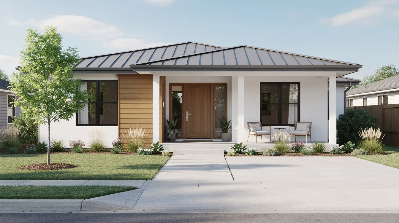
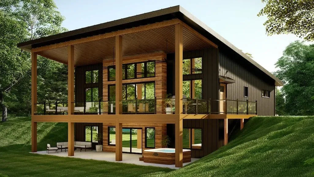
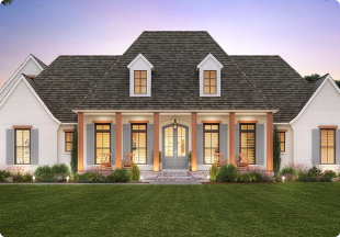
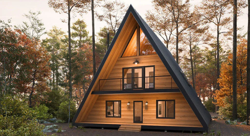
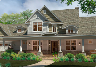
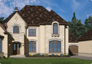
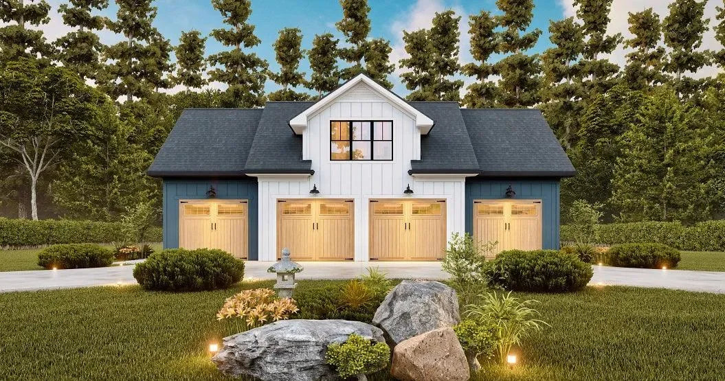
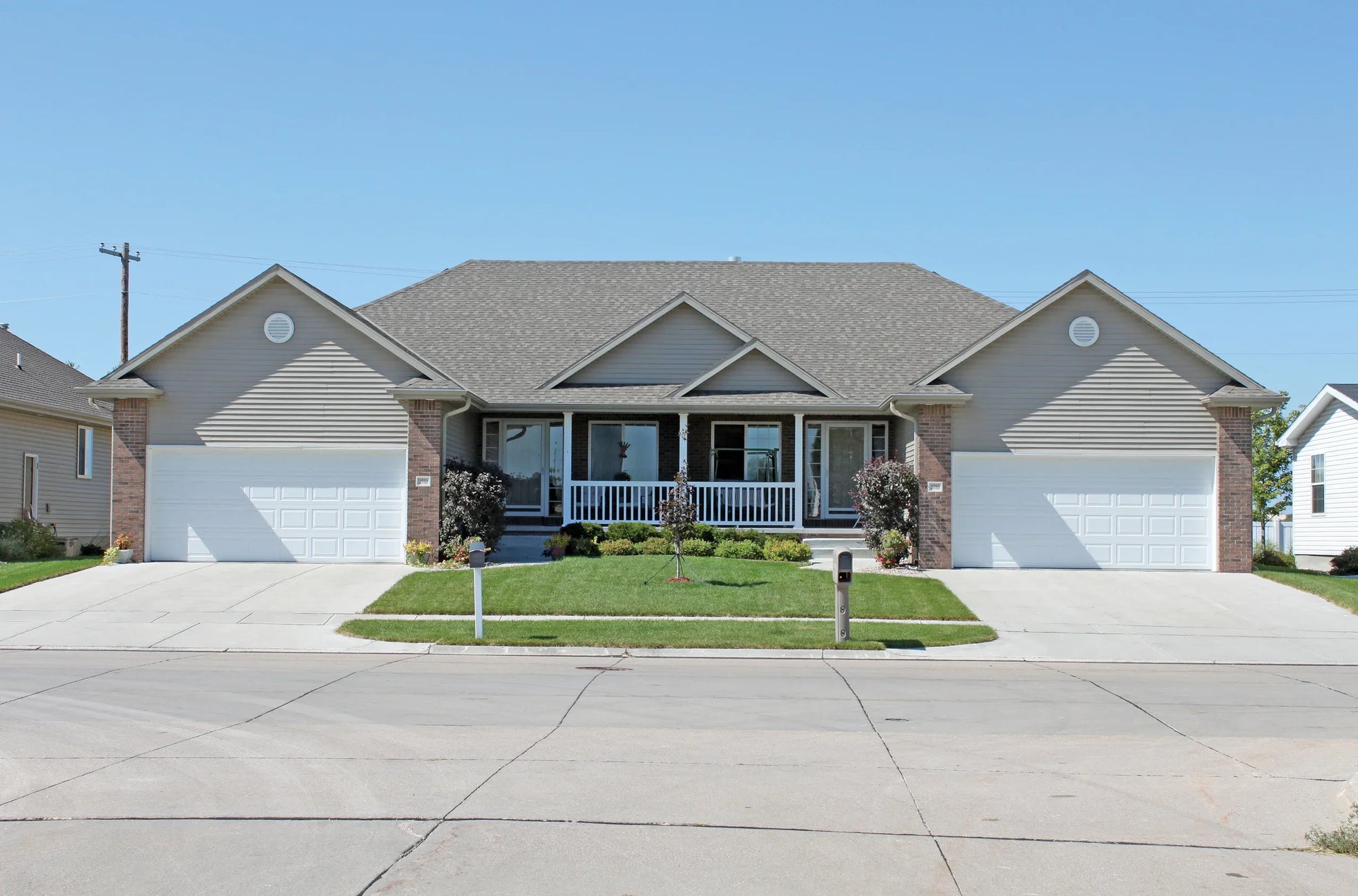
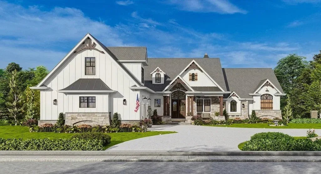
Exterior Elevations: Curb Appeal on Paper
Elevation drawings show straight-on views of each side: front, rear, left, and right. These aren’t perspective renderings—they’re flat technical drawings that document every exterior detail.
Elevations reveal:
-
Exterior materials (brick, stone veneer, lap siding)
-
Roof shapes and pitch (e.g., 8:12 slope)
-
Window styles and shutters
-
Entry details including the front door design
-
Overall height from grade to ridge
Vertical dimensions on elevations indicate floor-to-eave height, window sill heights above finished floor, and roof peak elevation. Compare elevations to floor plans to understand where key rooms sit relative to the street and where large windows capture views.
The renderings on Archival Designs’ website correspond directly to these technical elevation drawings in the blueprint set. If you love the curb appeal in the rendering, the elevation drawing documents exactly how to build it.
Sections and Detail Callouts
A section drawing slices vertically through the building, showing how floors, walls, and roofs stack. Think of cutting a house in half and viewing it from the side.
Section drawings clarify complex spaces:
-
Two-story great rooms with volume to the roof
-
Stairwells connecting different levels
-
Bonus rooms over garages with sloped ceilings
-
Basement-to-main-floor transitions
Look here to confirm floor-to-floor heights, how stair runs connect levels, and whether structural elements like beams or headers impact your design ideas.
Small detail callouts—circles or flags with numbers like “3/A-201”—link specific points on floor plans to enlarged details on other sheets. These enlarged views might show wall assembly layers, window head conditions, or foundation connections. Reviewing at least one section and its referenced detail helps you understand how the plan translates into real construction.
Common Blueprint Symbols, Abbreviations, and Legends
This section serves as a practical cheat sheet for frequent symbols and abbreviations on architectural plans.
|
Abbreviation |
Meaning |
|---|---|
|
WIC |
Walk-in closet |
|
WH |
Water heater |
|
HVAC |
Heating, ventilation, air conditioning systems |
|
CLG |
Ceiling |
|
OPT. |
Optional (not included in base design) |
|
TYP. |
Typical (applies to all similar conditions) |
|
REF |
Refrigerator |
|
DW |
Dishwasher |
|
W/D |
Washer/dryer |
|
GFI |
Ground fault interrupter outlet |
Electrical plans use their own symbols: circles with “S” for switches, circles with lines for electrical outlets, and various symbols for ceiling fixtures. These appear in a separate legend on electrical sheets.
While Archival Designs uses industry-standard notation, each plan includes a legend or notes area. Always check this first before assuming you understand every symbol.
Why the Legend Is Your Best Friend
The legend is the dictionary of a specific plan, decoding all custom symbols, line types, and abbreviations used on that set of drawings.
When opening an unfamiliar plan, find the legend immediately—often on the cover sheet or first floor plan page. It clarifies:
-
Wall types and hatching patterns
-
Door symbols and swing notation
-
Window symbols by type
-
Fixture abbreviations
-
Electrical symbols
-
Optional feature markers
Anything marked “OPT.” on an Archival Designs plan indicates an optional element—perhaps a bonus room, expanded porch, or alternate garage configuration—not automatically included in the base design. Understanding these options helps you on the same page with your builder about what’s standard versus upgraded.
Keep a printed or digital copy of the legend handy while reviewing the rest of the plan set. A seasoned designer memorizes common symbols, but beginners benefit from quick reference.
Using Your New Skills to Choose and Customize a House Plan
Blueprint-reading skills transform how you shop for house plans. Instead of relying solely on pretty renderings, you can compare floor plans based on room dimensions, circulation paths, and structural elements that affect future modifications.
When browsing Archival Designs’ catalog, use your new knowledge to:
-
Filter by square footage knowing that living area excludes garages
-
Evaluate bedroom sizes against furniture you already own
-
Identify load-bearing walls versus movable partitions
-
Spot potential modifications before purchasing
Print a floor plan and sketch furniture placement to scale. That 14’×16’ primary bedroom works for a king bed, but can you also fit the reading chair you want? Testing layouts on paper prevents expensive surprises.
Once you understand where structural elements fall, you can have focused conversations about plan modifications. Archival Designs offers modification services and cost-to-build estimates—both easier to request when you can reference specific sheet names, room dimensions, and existing conditions.
When to Ask for Professional Help
While this guide helps you read plans, interpreting structural safety and code compliance requires licensed professionals. Interior designers can help with furniture placement and finishes, but structural changes need engineering review.
Contact local building officials, engineers, or contractors to adapt any plan to local codes, climate conditions, and site specifics. Archival Designs can prepare modification quotes if you need to move walls, change foundations, or adjust rooflines—but local professionals must verify compliance.
Bring printed markups of specific sheets and dimensions when meeting with builders. Circling the area you want to change and noting the sheet number prevents miscommunication. When you dive deeper into discussions with professionals, your blueprint literacy makes those conversations productive rather than confusing.
Better blueprint understanding leads to smoother construction and fewer surprises. You become an informed participant in building your dream home rather than a passive observer hoping everything works out.
Frequently Asked Questions
These FAQs address common beginner concerns not fully covered in the main sections above.
Do I Need Full-Size Printed Blueprints, or Are PDFs Enough?
Full-size prints work best for builders on the construction site who need to spread drawings across sawhorses and mark them up with pencils. PDFs are ideal for preliminary review—you can zoom to 200% on a large monitor or tablet and examine details without eyestrain. Archival Designs offers both digital and printed blueprint packages, and many customers start by reviewing PDFs before ordering full prints. Most building departments still prefer printed sets for official permit submissions, though local rules vary slightly by city and county. Coordinate with your builder to decide how many printed sets you need before construction begins.
Can I Use One Blueprint Set to Build the Same Plan Multiple Times?
Blueprint licenses from stock plan companies like Archival Designs are typically for a single build unless you purchase a multi-use license. Professional builders who want to repeat a design across several lots should contact Archival Designs to discuss builder discounts and re-use terms. Keep in mind that reusing a plan in different jurisdictions may require local engineering updates or code adaptations even if you own the multi-use rights. Check the specific license language included with your plan purchase before planning multiple builds.
How Do Blueprint Revisions and Versions Work?
Each blueprint set is created for a specific revision date, shown in the title block as something like “Rev. 2.1 – 04/15/2026.” If you request modifications through Archival Designs, an updated version will be issued with a new date or revision note in the title block. It’s critical that everyone on the project—builder, engineer, trades—works from the same latest version. Clearly label or discard older printed copies once revisions have been made to avoid building from obsolete drawings.
Will My House Plan Blueprint Automatically Meet Local Building Codes?
Archival Designs plans are drawn to generally accepted residential standards, but they cannot automatically match every local building code or HOA guideline. Local requirements vary widely across U.S. states and cities, especially for wind loads, snow loads, seismic conditions, and energy efficiency. Have a local design professional or engineer review the blueprint and make required adjustments before permit submission. Archival Designs’ modification team can help adjust a plan so local professionals can finalize it more easily.
What If I Can’t Visualize the Space Just from the Plan?
Many beginners struggle to picture three-dimensional spaces from two-dimensional drawings—that’s completely normal. Try measuring out room dimensions with tape in your yard or current home to experience the actual size. Sketch furniture on graph paper at scale, or use basic floor-plan apps to test layouts digitally. The plan images and renderings on Archival Designs’ website help bridge the gap between the blueprint and the finished home. Don’t hesitate to ask your builder or a design professional to walk you through the drawings, pointing out ceiling heights, window views, and key sight lines until the spaces click in your mind.


